| An
experiment on a pair of Jensen RP-201 driver/horn assemblies that I've
had for about 30 years.
The horns are cast iron and seriously need to be damped. A wood clamp was applied to them during the tests for that reason although the ringing was muted to inaudibility with the horn mouth resting in its flange. When mounted on a baffle, sufficient damping should be achieved. The horn seems to be exponential according to calculations made from the throat and mouth areas and the length of the horn. The cutoff frequency is 665 hz. derived from the above. However, mounted on a baffle, the useable low frequency limit can be as low as 600 hz. which seems to be supported by the frequency responses below. There, the response at 600 hz is about 5 dB down from the passband between 800 hz and 5500 hz. It can be safe to assume that Jensen would have recommended a high pass filter of 800 hz.
|
PHOTO 1
 |
PHOTO 2
 |
| FIGURE
1
Two impedance curves for each unit; curves 2 (green) & 21 (blue) are for drivers only 1 & 2, respectively. Curves 3 (black) & 22 (red) are for the driver and horn assemblies, 1 and 2, respectively. The differences between the pairs is attributed to different materials and aging of the diaphragms, both being phenolic and subject to aging. The units were disassembled but the diaphragm assemblies weren't removed as it wasn't known if they are keyed and shimming them to the pole piece for reassembly can be a chore. Since no buzzing was heard during the tests as well as none being heard when a very low level (<1w) 10 hz signal was applied, foreign material in the gap was considered negative.
|
 |
| FIGURE
2
Two response curves, 7 (green) & 26 (black) in the upper group are all measured with a gated response to remove room reflections and all are smoothed at 0.25 octave. The red curve (29) between them is a scalar average of the other two. The light green curve, 28 is measured at 1w 2m. Note the 6 dB drop in level, indicating the LMS is quite capable of removing room reflections. Typically, in a room, the level will drop by about 3 or 4 dB when the distance from the source is doubled. The 6dB drop only happens in a non reverberant field. The sudden drop below 550 hz is due to the gating limitations. As the distance from the mic to source is increased, the difference between the incident wave and the first reflection approach equality and the system can't get a good sample. It tried between 550 hz and 475 hz but eventually failed, which was expected. |

|
ADDENDUM ADDED AUGUST 23, 2023
| This
addendum was added due to an AK member referencing this page which
originally dates to August, 2015. From that which he said, I got
the feeling that the page was incomplete, which, now that I think of it,
it is. Since then, acquisition of a CLIO analyzer and a computer
operated oscilloscope, PicoScope had been made. The Tektronix 465
would have done much the same as the Pico but nowhere as easy.
This is especially true of taking a photo of the 465 screen. There
is also a Tektronix AA501 distortion analyzer but again, not as easy to
use as that which is included in the CLIO.
So, this morning, August 23, 2023, I awoke around 6 AM and got busy. The only reason for the 3-way design was to be able to get a better idea of how the Jensen horn sounded.
|
| PHOTO
3
The woofer is not used here; it's a remnant of an earlier project. To satisfy anyone's curiosity, it's one of two Wharfedale W12RS woofers dating to the sixties and used in their W series systems. |
PHOTO
4
This horn was used for comparison. Since this page is about horns, a description of this system will be placed at the bottom of this page so as not to clutter the main topic, the Jensen. |
| 0.6W was max
allowed to keep the mic and/or its pre-amp from going into distortion.
This equated to an SPL of 124dB at the mouth of the Jensen and 121dB at
the mouth of the K400.
The power transfer was calculated at the nominal impedance of each horn. |
|
|
|
|
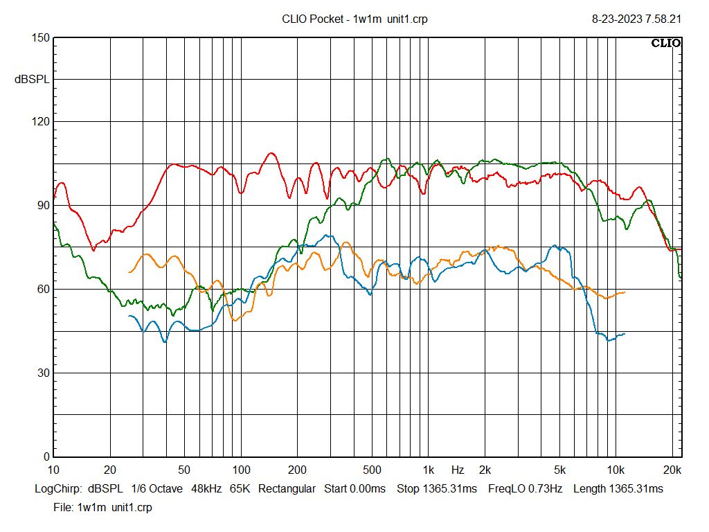
| FIGURE
5
Jensen rp-201 1w1m BLK-unit 1 GREY-THD RED-unit 2 ORN-THD A comparison of the two RP201s. The THD curves equate to about 1.4% |
|
| FIGURE
6
1w1m RED-corner horns ORN-THD GREEN-jensen BLU-THD The THD on these Klipsch K55V drivers also equate to about 1.4%. The curve vertical spacing may be deceiving but this chart is 15dB/div whereas the previous one is 10dB/div. Also, it should be noted that the bass and treble extension of the upper red trace was obtained a few years ago and the bass horn and the T350 were also present. |
|
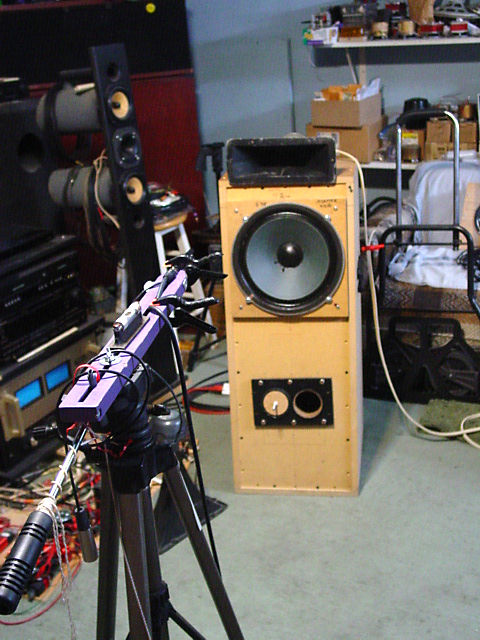
| The
completed three way. I know it look terrible but it works a lot
better than it looks. The clamps on the Jensen are to dampen
ringing and it does ring, just like a bell since it's not baffle
mounted.
|
|
| PHOTO
5
|
PHOTO
6
|
| FIGURE
7
Some responses run at 1w1m during crossover mods. All responses are gated with exception of the left pink trace and the blue trace. The blue trace is presented to show the effect of the room which can be seen if compared to the gated dark pink trace above 300hz. The light pink trace below 300hz is a summation of the near field responses of the woofer and the vent. The grey trace above the pink and blue shows the hump that demanded the use of a notch filter in the mid-range section of the crossover. The black trace at the top is the response of the RP201 with no filters applied. It was run Aug. 30, 2015. It can be seen that this unit is far too efficient for most, if not all passive woofers and many tweeters. Even the Klipschorn has its mid-range horn attenuated by 6dB which matches it well to the T35 tweeter. The efficiency of the bass horn takes care of the low end. Attempts at removing the several dB drop between 200hz and 500hz proved fruitless.
|
|
| Such
attempts were bringing the Jensen closer to the woofer and even aligning
the voice coils in the vertical plane. (see photo 7)
That, of course, was just a matter of academia as it has little to do with the performance and evaluation of the Jensen. After all was done with theory and design, the final test was performed by connecting this system to the audio system. In short, it performed well, actually better than expected. the main fear was that the horn would sound honky. It didn't. One possible reason is the 800hz second order filter despite that the horn does well to 500hz. However, frequency responses and THD don't tell the whole story; test equipment doesn't have ears. |
 |
|
Several types of music were played and the real acid test, in my opinion, is how well it performs with female vocalists. This mono system does extremely well even a levels as high as 97 dB. In fact, since the apparatus to duplicate this system is available, I'm 'a-gonna' do just that and bring them into my living room/dining room which measures 31' by 17' and one of the long walls is only a third of a wall which opens into the hallway. I just love it when friends are astounded at how good some 60 year old loudspeakers can sound. OH. BTW, I'm single so there's no WAF (Wife Acceptance Factor)
|
|
| PHOTO
7
I did wonder about the effect of the shelf protruding above the woofer but not enough to figure out how to hold the horn without it. There was little to no noticeable difference in the responses run with and without the horn's voice coil being aligned with that of the woofer. Then, there's the 12" difference between the voice coils of the horn and the tweeter. Consider a symphony orchestra. There are about 30 first violinists on the left. From any position in the concert hall, the distance from the front violinists is shorter than those at the rear. Wirth all violinists playing the same notes at any time, the sound from each violinist will be heard at different times, much greater than the time delay caused by 12 inches between a mid and tweet. However, with percussive sounds, this can be a problem. In the 40's or maybe 50's, a Hollywood studio was using vary large cabinets for the woofer,. The high frequency horn was on top of the cabinet. When listening to the sound track of a tap dancer, a double click of each tap was noticed. This was eliminated by moving the high frequency horn forward to align the two voice coils. Another such problem with time delay, aka group delay, will go unnoticed with music but if that music is associated with video, that delay can un-sync drum beats and lip movements with the sound. It has been my contention for decades that too many people pay too much attention to their systems that they miss the music.
|
|
| FIGURE
8
The crossover. The component impedances shown at the lower left are the values used to calculate the filters' components. |
|
| The
Klipsch Type Corner Horns
They are the third set built prior to the early 80's, the first being in the early 70's. Living in an apartment at that time, power tools were taboo. So, what was used was a carpenter's saw, a keyhole saw, a 6 inch block plane and a hand operated drill. At that time, I was newly married so there was a WAF, Wife Acceptance Factor or perhaps a tolerance factor. The internet didn't exist then so papers on horns were accessible through inter library loan, which took time. I lucked out and found out that Vassar College had all of them. Living within 15 miles of the place, I went there but couldn't gain access to the library as I wasn't a student. As Providence would have it, a student there heard of my plight and made copies of some 30 papers, most of which comprised many pages. I still have those papers, some dating as far back as 1924. These were all referenced by Mr. Klipsch. This last pair, as were the others, built from scratch, using horn theory. They are not copies of the venerable Klipschorn. These behemoths will dwarf a Klipschorn, which has a bass horn length of just under 4 feet; these have a bass horn of 7 feet. The original uses two flare rates, these have three. That was necessary to keep the horn as short as possible. The tweeter is an Electro-Voice T350, which is about 3 dB more sensitive than the T35. The midrange drivers were originally Electro-Voice 1824M units, decades later replaced with Klipsch K55V drivers which were modified by Mr. Klipsch to get down to 400hz. In my early years, I knew he modded them but not how. Years later, I found out but was too skittish to open the 1824Ms. When a pair of K55V drivers appeared on the bay, I couldn't resist. The mid-range horn is hand made with wood, actually, MDF, after soaking the panels in water to bend them onto a jig while they dried. The low frequency driver is a JBL 2205, now the 2226. The KLipschorn unloads at about 47hz while these behemoths unload at 36hz. In the table of contents are several links to horns. Another two pages are listed in the Loudspeakers Index close to the bottom and regarding horn loading the Faital 3FE22. Viva La Horn. Horns were good enough for Joshua at the Battle of Jericho, so they're good enough for me.
|
Back to the loudspeaker main page